
A garage is a "surface" problem, a tunnel is a "line" problem, and a high-rise is a "height" problem. The root causes of blind spots differ, so the signal distribution method, antenna selection, and component requirements are completely different. Applying the same solution to all three scenarios will almost certainly fail in one of them.
This isn't theoretical. In an underground garage, signal attenuation comes from concrete slabs and metal vehicle bodies absorbing and reflecting energy. In a tunnel, attenuation comes from the waveguide effect of a closed tubular structure. In a high-rise, the core tube and elevator shaft act as natural shields. RF signals propagate differently in these three structures, and the component selection logic must follow.
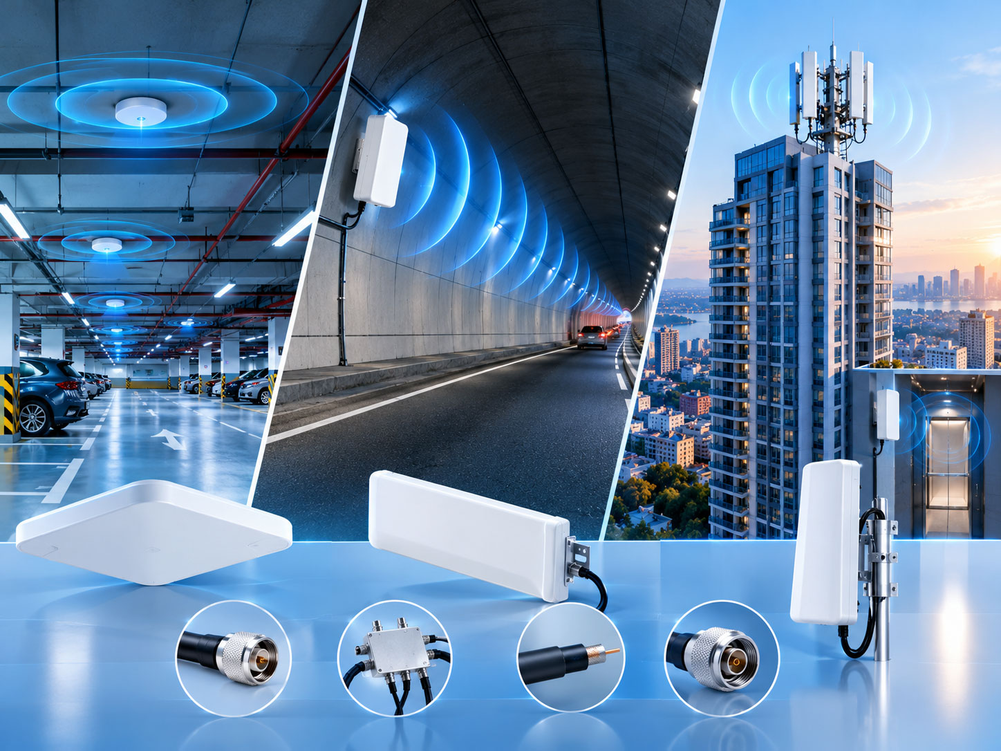
An underground garage sits below ground level. The concrete slabs and soil above attenuate signals by more than 20–30dB. For a two- or three-level basement, the ground-level signal may already be attenuated by 10,000 times (40dB or more) by the time it reaches the garage. Ramps and columns create additional shadow areas.
But the garage structure has one characteristic: open space, limited floor height, and obstructions mainly from the column grid. The signal needs uniform horizontal distribution over a large area, not long-distance transmission in one direction. This is fundamentally different from tunnels and high-rises.
The mainstream garage coverage solution is BDA/DAS plus passive distribution. The source is distributed through feeders to multiple antenna nodes, each covering a column-grid area. The key lies in antenna density and mounting position.
Antenna position matters more than gain. Garage ceiling height is typically 3–4 meters. A ceiling-mounted omnidirectional antenna covers a radius of about 8–15 meters depending on power and band. If the antenna is hung below pipes or blocked by ductwork, the coverage radius is cut in half. A common engineering practice is to place antennas above the driving lane, using the relatively open lane space to radiate toward parking spaces on both sides, rather than placing the antenna directly above a parking spot.
The core requirements for passive components in a garage are cost control and installation convenience.
The core characteristic of a tunnel is the closed tubular structure. Besides normal path loss, signals in a tunnel experience the waveguide effect — signals bounce back and forth between tunnel walls, creating multipath interference. In this environment, a conventional omnidirectional antenna at the tunnel entrance can only illuminate a few dozen meters before the signal drops off rapidly. Increasing transmit power doesn't solve the problem, because the attenuation rate in a tunnel is much faster than the power increase.
There are two technical routes for tunnel coverage: leaky feeder cable and high-gain directional antenna.
Leaky feeder is installed along the tunnel wall. Its outer conductor has periodic slots, allowing signal to leak uniformly along its entire length, forming a continuous distributed antenna. Its advantage is uniform coverage and suitability for curved tunnels, with small signal fluctuation along distance. The cost is shorter coverage distance — the effective coverage of a single leaky feeder segment is limited by coupling loss and attenuation per 100 meters, and amplifiers must be spaced at intervals to extend reach.
High-gain directional antennas have high gain and long coverage distance, but are only suitable for straight tunnels. If the tunnel curves even slightly, the beam cannot reach around the bend. Also, directional antennas produce signals that are too strong near the antenna and attenuate quickly at the far end, resulting in less uniform coverage than leaky feeder.
The practical selection logic is: for long straight sections with few curves, directional antennas can reduce equipment count; for tunnels with many curves and a need for continuous uniform coverage, leaky feeder is the more reliable choice. Metro tunnels, with many curves and multi-system coexistence requirements, make leaky feeder the mainstream solution. Highway tunnels have longer straight sections, so directional antennas are used more often.
Leaky feeder selection depends on three numbers: coupling loss, attenuation per 100 meters, and mounting position.
The core requirements for passive components in tunnels are low insertion loss, high power handling, and low PIM.
High-rise blind spots come from two sources with completely different natures.
First source: height. Outdoor macro antennas are optimized with a downtilt for ground coverage. Upper floors of a high-rise may fall outside the vertical coverage of the macro main lobe. The signal from the macro to the high-rise interior must penetrate the building envelope, and the loss varies with floor height.
Second source: core tube and elevator shaft. In a high-rise tower laid out around a core tube, the elevator shaft and stairwell are natural metal shields. The elevator car itself is a Faraday cage, and the shaft adds a waveguide effect. Conventional indoor distribution antennas installed in corridors or rooms can hardly penetrate effectively into the shaft.
High-rise coverage must be handled floor by floor, with a separate plan for the shaft.
Floor areas: Conventional DAS or digital indoor distribution, with antennas deployed per floor. For long, narrow high-rise residential buildings where middle units are prone to blind spots, a combination of rooftop spotlight antennas pointing downward plus ground-level spot base stations pointing upward can achieve vertical continuity.
Elevator shaft areas: This is the "hard bone" of high-rise coverage. The conventional approach is to install a micro base station or a remote unit of a repeater inside the shaft, so that the signal is generated inside the shaft. A medium-power (2W class) device can independently cover an elevator shaft of about 30 floors; a micro-power solution requires a car-mounted unit for relay amplification. The key point: the signal must be generated inside the shaft, not "shone in" from outside.
Vertical beam control: For super high-rise buildings, a fixed downtilt outdoor macro cannot cover both low and high floors simultaneously. In the 5G era, configurable vertical beams have emerged — multiple vertical narrow beams are added on top of the horizontal beam, flexibly configured by floor height to improve vertical coverage.
The core requirements for passive components in high-rises are low PIM, wideband, and compact size.
Mistake 1: Taking the garage's "good enough" solution into a tunnel.
Microstrip splitter insertion loss is acceptable in short garage links, but on a long tunnel leaky feeder link, every extra 0.3–0.5dB is amplified by downstream attenuation, ultimately shortening coverage distance or requiring additional amplifiers.
Mistake 2: Using an omnidirectional antenna instead of a leaky feeder in a tunnel.
The radiation pattern of an omnidirectional antenna does not match the tubular structure. The signal is too strong near the antenna and attenuates rapidly at the far end, failing to form continuous coverage. Directional antennas are feasible in straight tunnels, but omnidirectional antennas are never a good choice in any tunnel scenario.
Mistake 3: Installing only corridor antennas for a high-rise elevator shaft.
The metal shielding of the elevator car plus the waveguide effect of the shaft means the signal radiated from a corridor antenna into the shaft can be attenuated by more than 30–40dB. If the "signal generated inside the shaft" problem is not solved, elevator coverage will always have gaps.
Mistake 4: Ignoring the cumulative effect of PIM in enclosed spaces.
The long, narrow structure of tunnels and utility corridors causes PIM products to bounce repeatedly between walls. The actual impact of PIM from the same set of components is more severe in a tunnel than in an open garage. Using -150dBc components for multi-system combining in a tunnel carries a high risk of raising the uplink noise floor.
Garage: Decide antenna positions first, then calculate power. Antennas blocked by pipes or ductwork are the number one cause of garage coverage failure. During design, review the MEP (mechanical, electrical, plumbing) drawings first, then perform the link budget after antenna positions are fixed.
Tunnel: Use 95% probability coupling loss for leaky feeder. The 50% coupling loss is the "median"; engineering margin must be based on the 95% value. Any deviation in leaky feeder mounting distance from the tunnel wall must also be included in the coupling loss budget.
High-rise: Design a separate coverage plan for the elevator shaft. Do not treat elevator coverage as a "side effect" of floor coverage. Install a micro base station or remote unit inside the shaft, sharing the source with the floor DAS, but plan the RF link independently.
One rule that applies to all three scenarios: Confirm the PIM test conditions. A "-155dBc" rating must specify that it was measured at 2×43dBm. A -155dBc measured at 2×20dBm will degrade by 5–10dB or more at actual transmit power levels above 40dBm.
Tags :
هل لديك أي أسئلة ؟
اتصل بنا : +86 551 65329702